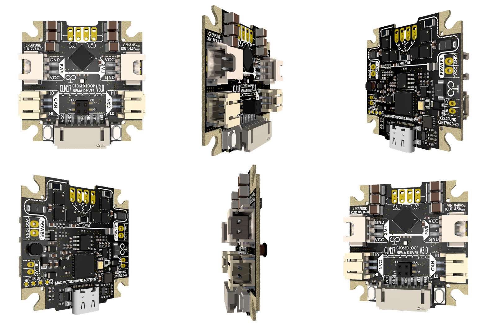
Early Access
V3.0
šŸ“¦ Estimated Shipping: End June 2026

CLN17 V3 Motor Driver

$39.49
excl. Shipping
$36.99 3+ units
$32.99 10+ units
$30.99 25+ units

A compact, rear-mountable, cost-effective closed-loop high-current Stepper/BLDC motor driver, featuring multi-level protection and a comprehensive set of communication interfaces

Stepper 3-phase BLDC PMSM
  • Driving capability: 3.2A RMS, 4.2A PEAK Up to 60W
  • Power stage: 6-48V, Discrete MOSFETS <50mR channel resistance
  • Feedback: 21-bit Absolute encoder
  • Daisy Chain support: Power and CAN connectors
  • Expansion board port: Power and UART signals for custom functionality
  • Protection: Overvoltage, Overcurrent, Overtemperature, ESD
  • Universality: Motor Type and Phase connection auto-detection
  • External encoder supply: 6pin connector has 5V 60mA source
STEP-DIR-EN USB CAN-FD USART I2C SPI ABZ SWD

Kit Contents

Standard Kit Includes:

  • 1Ɨ PCBA CLN17 V3
  • 1Ɨ Enclosure (aluminum base + plastic cover)
  • 2Ɨ DIN7991 M3Ɨ8mm screws
  • 2Ɨ N48H 120°C diametrically magnetized magnet
  • 1Ɨ 100cm wire set for all interfaces (CAN, CONTROL, POWER)
  • 1Ɨ 3cm wire for stepper motor
  • 1Ɨ Adapter for POLOLU drivers
  • 1Ɨ Kit of motor connectors: Horizontal XT2.5 4Pin or Screw terminal (unsoldered)

Additionally Required:

  • 1Ɨ Programmer + cable (+$10) — At least 1 required per order for firmware flashing. More info here

Optional Add-ons:

  • High quality stepper motor — No sourcing issues, same motor for all drivers means it is easier to tune your system

āš ļø Important Information

⚔
Voltage Limitation: For stepper motor control, maximum effective voltage applied to motor is 65% of supply voltage. E.g. for 48V supply effective voltage will be 31V
šŸ”§
Firmware Status: Firmware is in WIP status. There may be any API changes and ongoing improvements in functionality. Firmware is open-source so you will be able to make update any time
šŸ”Œ
Motor Connector: Motor connector will be NOT soldered. There will be 2 types of connectors in kit: Screw terminal and horizontal XH connectors. You should be able to solder them yourselves for your specific application
šŸŽØ
Design Changes: PCB color and component placement is subject to change
šŸ”“
ATTENTION! EARLY ACCESS CONDITIONS:
  • This is an ENGINEERING SAMPLE version, which is distributed ONLY to developers and testers, not intended for plug & play operation with all functionality
  • All boards will undergo QC before shipment to eliminate defects
  • Shipping and taxes are paid separately
  • If defects or any technical and quality issues are found, please report them in Discord previously
  • You need at least one programmer kit to ensure you can change firmware and have access to internal registers for debug/development
  • If you buying this board please make sure you will fill form below to ensure that project developer can contact you in case of troubleshooting etc

Share your use case to improve driver

This 20min survey helps us understand how you'll use the driver — your setup, requirements, and edge cases directly inform hardware decisions, firmware priorities, feature support prioritization, usage examples, and who gets the first batch of drivers.

Note: The more detailed your feedback, the more valuable it is for the project. Specific use cases, technical constraints, and real-world scenarios help us build a better product for everyone.

Section 2 — Demand

Helps us evaluate demand and set long-term project priorities

A high-quality NEMA17 motor with back-mounted driver will add $15 to each kit

A USB programmer kit ($10) can be used as a backup firmware flashing tool and fast debug tool. More info here: https://hackaday.io/project/192857

Price 3
1
Highest
2 3 4 5
Lowest
Size / Form Factor 3
1
Highest
2 3 4 5
Lowest
Functionality / Features 3
1
Highest
2 3 4 5
Lowest
Open-Source 3
1
Highest
2 3 4 5
Lowest
Community Support 3
1
Highest
2 3 4 5
Lowest
Ease of Integration 3
1
Highest
2 3 4 5
Lowest

Section 3 — Current Setup & Pain Points

Understanding what you're using now and what frustrates you guides our feature priorities.

Section 4 — Application

Your specific use case determines motor parameters, control modes, and edge cases we need to test.

Number of stable positions / full steps per revolution

Section 5 — System Integration

Defines which interfaces, protocols, and features we prioritize in firmware development.

Section 6 — Business Context

Helps us understand commercial needs, support expectations, and long-term commitments.

Section 7 — Special Requirements & Final Notes

Captures hardware preferences, missing features, and your honest feedback on the industry.

Board connectors orientation

Motor connector type

Section 8 — Contribution Type

Determines how you'll participate in the early access program and what value you bring to the project.